Using Design Options for an Interior Layout
In this example, we have reached a stage where a basic Design for a classroom has been made.
The client now requires Options for this Interior Layout.
The client now requires Options for this Interior Layout.
(To follow this tutorial, i suggest you draw this same layout for yourself and follow the same names to better understand the process)
 By using Design Options, we can comfortably create several options and see them in different views, schedules etc.
 To begin using Design Options, firstly activate the Design Options Tab on the toolbar.
By clicking on the Design Options Button, the dialog box will appear where we can categorize different options related to this design project.
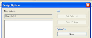
Option Sets can be created for various parts in this same Project. Like Classroom, Cabin etc. Interiors as well as architectural.
Assuming that we want to create design options for this interior layout, we’ll create a New Option Set by clicking on NEW under Option Set. In this example we shall rename the same to CLASSROOM A.
If we want to present two options for this Classroom A, Click on NEW under OPTION. You will see OPTION 1 & OPTION 2 created for the same. Rename these two as per the ones in the figure below.
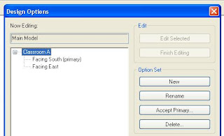
We have now explained Revit that we are looking forward to creating two different layouts viz, Facing South & Facing East for this Classroom A. (These names are as per our understanding. Revit doesn’t understand these names, really!) Click Close for this dialog box.
And now comes the real cool Revit part of the process.
Now select all the desks and chairs in this layout (they should highlight in RED colour) and Click on ADD TO DESIGN OPTION SET button. Here Revit shall verify which design option you want to add these to. Since we have only one OPTION SET assigned as yet, click on OK.
Now if you try selecting the Chairs & Desks in the layout, they will no longer be selectable. This is because they are now a part of Design Options! They have been added to both the Options (Facing South & Facing East) for the Option Set Classroom A.
Our objective in this example is to have one option which shows us the current layout and the other option which shows the new layout which desks and chairs facing East-side.
For this purpose, its best suited to create two separate views (duplicating floor plans).
Do that as per the illustration below.
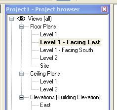
Go to view LEVEL 1 – FACING SOUTH. Type VG on the keyboard to access the Visibility & Graphics for this view. On the top you shall see a new tab called DESIGN OPTIONS. Access it and select FACING SOUTH for CLASSROOM A.
Similarly assign FACING EAST in the VG for the view LEVEL 1 – FACING EAST.

Similarly assign FACING EAST in the VG for the view LEVEL 1 – FACING EAST.

By duplicating the views and setting their correct visibilities we have made it clear for us to understand which view shows what. Do a window tile to see the two views side by side.
There isn’t much change in the Option FACING SOUTH. All the desks and chairs are rightly facing downwards. But in the view FACING EAST, we need to rotate the desks and chairs to face on the right side.
On the design options toolbar, click on EDIT OPTION and select the option
CLASSROOM A: FACING EAST
With this, the desks and chairs in the view FACING EAST are darkened and the rest of the objects in other views are grayed out immediately.
Make suitable changes to the desks and chairs (rotate them to face East-side). Once you are through with the modifications for the same, click on EDIT OPTION, to complete the modifications.
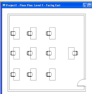
Now you can view both the layouts simultaneously.
There isn’t much change in the Option FACING SOUTH. All the desks and chairs are rightly facing downwards. But in the view FACING EAST, we need to rotate the desks and chairs to face on the right side.
On the design options toolbar, click on EDIT OPTION and select the option
CLASSROOM A: FACING EAST
With this, the desks and chairs in the view FACING EAST are darkened and the rest of the objects in other views are grayed out immediately.
Make suitable changes to the desks and chairs (rotate them to face East-side). Once you are through with the modifications for the same, click on EDIT OPTION, to complete the modifications.

Now you can view both the layouts simultaneously.
More to come on this soon.... !!
